
An excellent sounding and popular VCO (voltage
controlled oscillator) module. The design was originally inspired
by the classic sound of the Mini’s VCOs with the central core of
the oscillator being somewhat similar. However, a great many
things have been added and changed to make it more suitable for a
modern modular system.
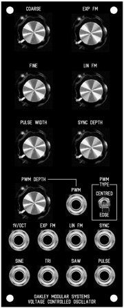
Four output waveforms are provided
simultaneously; falling ramp sawtooth, triangle, pulse and
sinewave. Output levels are 10V peak to peak, in common with most
modular systems.
Apart from the usual fixed 1V/octave
modulation input, a fully variable exponential input is available
as well as a fully variable linear modulation input.
Slave synchronisation is easily obtained by
inserting a falling sawtooth waveform into the SYNC input. This
input is level sensitive to allow different strengths of
synchronisation. A front panel pot is provided to control the
depth of the effect.
The pulse waveform can be modulated in two
ways. You can have either ‘centred’ or ‘edge’ modulation styles
selected by a front panel switch. The former will allow
modulation of both edges of the pulse output, while the latter
modulates only one edge. There is a useful and interesting
difference between the two settings when used with a rapidly
changing modulation signal like that from a fast LFO or an audio
rate VCO.
The pulse output also features a useful
method of maintaining average output level. This means that fast
sweeps of pulse width no longer produce any audible clicks as
they do on other VCOs you may have used.
Power (+/-15V) is provided to the board
either by our standard Oakley 4-way header or Synthesizers.com
header. Current consumption is approximately 35mA per rail.
The Oakley VCO in a natural finish 2U panel
showing an issue 7 main board with issue 5 socket and pot boards.
All pots are 16mm Alpha/Alps types
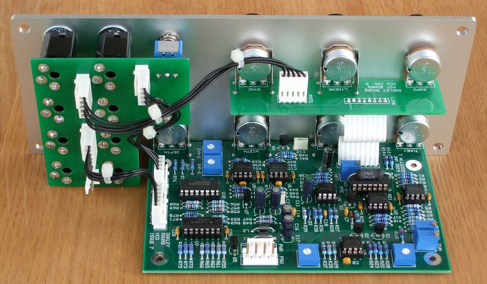
The PCB
The main board
size is 89 mm (deep) x 143 mm (high). The issue 7 board is a four layer design with
through plated holes, has tough solder mask both sides, and has
bold component legending for ease of construction.
The VCO module features uses a three PCB
set. Each PCB can be puchased individually. The three board
method allows all the wiring to be done with a special socket PCB,
special pot board PCB and 0.1″ flexible connections. The VCO
electronics are housed on the main board. The interconnection
between the main board and pot board is via a 8-way preformed
jumper interconnect. If you are building this module this system
will reduce assembly time by at least an hour and a half!
Some people will wish to use this Oakley
design in a non standard format, such as fitting it to another
manufacturer’s rack or one of their own invention. This is
perfectly easy to do. Simply do not purchase the socket board or
pot board and wire the main board to the sockets as per usual.
Sound Sample Downloads
Some MP3 samples of the Oakley
VCO in action. The VCO was controlled by a midiDAC-2. Its output
was fed into an Oakley ADSR/VCA and then onto the desk for
recording. Only one VCO output is being heard, although for the
sync’d samples, another VCO was required to provide the master
frequency.
Sinewave output. Short sequence with light
reverb
Pulse output. Same short sequence with EG
sweeping the pulse width.
Pulse output, manually swept from 10% to 90%.
Short sequence with light echo.
Sawtooth output. The VCO you are listening
to is synchronised to a second VCO via its ‘sync’ input at a
fixed frequency. The first VCO is now a slave VCO. The coarse
frequency pot of this slave VCO is swept manually up and then
down.
Pulse output and modulating with a VC-LFO.
There are eight samples in this set. The first pair of samples
have the pulse width modulated by an sine wave LFO at a slow
speed and differ only by the position of the PWM type switch.
The first sound heard in the first pair
uses the ‘edge’ setting, while the second sound uses the ‘centred’
setting. Unlike the ‘edge’ setting, the ‘centred’ setting does
not introduce a varying phase shift which means there is no
perception of frequency modulation. As we can hear, the perceived
pitch shift in ‘edge’ mode is not that obvious at these lower
modulation frequencies.
The second pair of sounds is the same sound
but with a faster modulating frequency. Again, ‘edge’ is first
and then ‘centred’ and this time the difference is more
pronounced. The third pair of sounds is the same patch but at an
even higher modulation frequency. The difference is now very
obvious. The fourth sample is the previous patch but the switch
is moved between ‘edge’ and ‘centred’ repeatedly. The fifth
sample uses a triangle audio rate modulation from a slightly
detuned VCO. Again, the switch is moved between the two settings
to highlight to the difference in the sounds.
Project Downloads
Construction
Guide Our handy guide to building
Oakley DIY projects
Parts
Guide Our handy guide to buying
parts for Oakley DIY projects
Links to schematics are
available to purchasers of the PCB or module and will be sent via
e-mail when the board(s) are shipped.
Front Panel database
A Schaeffer front panel can be made for
this module. The databases can be found by downloading the
following links:
5U format in
traditional black
To read, edit and print these
files you will need a copy of ‘Frontplatten Designer’ from Schaeffer. Panels can be ordered via the program using its
secure online ordering system.
Schaeffer are based in Berlin, Germany and
can send panels to anywhere in the world. Delivery to the UK
normally takes around ten days. For North American users you can
also order your Schaeffer panels from Front
Panel Express.