
The ASV – Complete Synthesiser Voice
Constructional Difficulty: Large number of parts
and calibration required.
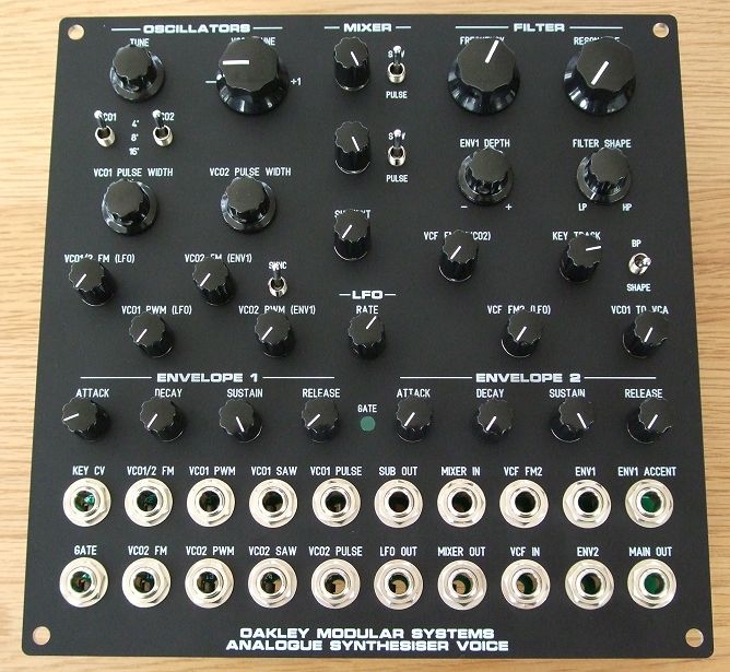
The prototype ASV fitted into a 5U wide
MOTM format printed front panel from Scheaffer. The knobs used in
this build are Davies 1900H clones (small), MXR clones (big), and
Davies skirted (medium).
The
Oakley Analogue Synthesiser Voice, or ASV, is a complete analogue
synthesiser in a 5U wide, or four MU width, module for the MOTM
and MU formats. It consists of the traditional synthesiser
architecture of two oscillators feeding a single filter, via a
mixer, and then to an amplifier. Two identical four stage
envelope generators (ENV1 & ENV2), and one sine wave low
frequency oscillator (LFO) act as modulation sources to control
the sound in a dynamically interesting way.
Each
voltage controlled oscillator (VCO) is based around a classic
sounding sawtooth core. VCO2’s frequency can be hard synchronised
to VCO1 by a front panel switch. Both sawtooth and variable width
pulse waves are generated. These are both available from the
socket field but only one from each VCO may be selected in the
audio mixer that feeds the filter. An additional triangle wave
from VCO1 can mixed with the audio signal from the filter prior
to the final amplifier.
The ASV
also has a sub-oscillator. This produces a triangle wave output
that is half the frequency of VCO 1, that is, one octave below
the pitch of VCO1. By default this is sent to the third level
control on the mixer although this can be overridden by inserting
a jack plug into the ‘mixer in’ socket. The sub-oscillator’s
output is also available on the socket field.
The
pitch of both VCOs may be controlled by a master tune control on
the front panel. Two octave switches independently control the
base pitch of each of the VCOs. Each switch covers a range of
three octaves. The pitch of VCO2 may also be offset from VCO 1 by
the VCO 2 Tune control. The range of this control covers just
over one octave from unison at the 9 o’clock position to an
octave above at around 3 o’clock.
Pitch
may also controlled by external control voltages (CVs) and
internal sources such as the LFO and ENV1. Front panel pots
control the depth of this modulation.
The
pulse wave output from each VCO can be manually controlled by the
pulse width controls. At their middle settings both pots will
produce a 50% pulse wave, ie. a square wave. The pulse width of
both VCOs can be dynamically altered with external CVs, or
internal sources. Both VCOs use special circuitry to make the
their average voltage output equal to zero. This reduces audible
thumping when the pulse width is modulated quickly.
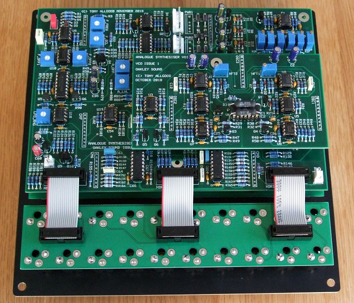
The ASV, here mounted on a MOTM format
panel, uses four printed circuit boards all parallel to the front
panel making for a shallow module.
The
audio mixer normally sends its output direct to the filter
although this can be broken by using the ‘filter in’ socket. In
this way it is possible to process the mixer’s output by taking a
signal from the ‘mixer out’ socket, feeding it through another
module, and then back into the AVS via the ‘filter in’ socket for
final processing.
The
voltage controlled filter (VCF) is a state variable design based
on the one in a classic synthesiser first seen in the early 1970s.
It has two basic modes, shape and band pass (BP). In shape mode
the output response is controlled by the Shape control. Fully
counter clockwise the response from the filter is -12dB/octave
low pass, and fully clockwise it is -12dB/octave high pass.
Between the two extremes are a variety of responses and half way
around, ie. the control is pointing upward, you get a notch
filter which attenuates a single frequency. The filter has a
separate resonance control where increasing amounts will
accentuate the frequencies heard around the filter’s cut off
point.
The
filter’s cut off frequency is controlled by a front panel pot and
several modulation sources including ENV1, LFO, and VCO2. The ‘ENV1
accent’ socket allows an external CV to additionally control the
level of ENV1 reaching the filter.
The
voltage controlled amplifier (VCA) shapes the volume of the
signal leaving the filter. It is solely controlled by ENV2. Both
ENV1 and ENV2 are triggered by a single gate signal present at
the gate input socket. If no jack plug is inserted into the gate
socket then both envelopes are held in their sustain phase, as if
they are permanently gated on. The gate LED will light green when
gate is active.
The ASV’s
LFO is a wide range oscillator that will go from very slow to
around 120Hz. It produces a sine wave output which is routed
internally to certain functions and is available on its own
output socket.
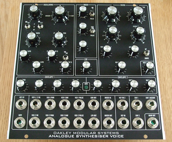
The
ASV fitted to a four unit wide MU panel.
The
module is built from four printed circuit boards populated by
through hole components. The four boards are: The double layer
pot/switch board which holds the front panel potentiometers and
switches, and some supporting circuitry. The four layer main
board which has the majority of electronics such as the filter,
envelopes, LFO, oscillator pitch control and sub-oscillator. The
double layer socket board which supports all twenty 1/4
jack sockets and is connected to the main board via three
detachable ribbon cables. And finally the four layer VCO board
which as its name implies has the core of the two voltage
controlled oscillators and pulse generators.
The
module requires +/-15V at around +/-160mA which is supplied via
two MOTM/Oakley, or MU, power headers. MOTM/Oakley power leads
are to be preferred as they are more rugged and can carry more
current without problems. Whichever you choose two power leads
are required for normal operation. No harm will come to the
module if only one power lead is connected but some functions
will not work.
The
main board and pot/switch board are both 203mm (wide) x 143mm (high).
Once completed the depth behind the panel of the module is
approximately 55mm.
Sound Samples
A simple riff manually played
showing the dry signal from the ASV. This is the filter in high
pass mode with the triangle output direct to the VCA turned up.
A bass drone. Two sawtooth
waves band pass filtered with the filter being modulated by the
internal LFO. Reverb is used for ambience.
A dry recording of the ASV’s
second VCO being pulse width modulated by the internal envelope.
The ASV doing the classic sync
sweep sound. A sawtooth waveform is used with the pitch of VCO2
being swept with the internal envelope generator.
A long recording of the ASV
playing a looped simple sequence while the filter’s and level
settings are manually tweaked. A very simple delay is used to
create that Berlin School vibe. About half way through I turn up
the sub-octave level. If you’re listening to this on half decent
speakers you’ll hear it.
A quick and dirty improvised
set with one overdub. The first track recorded is the sequence
line. This is just the ASV being played by a simple sequence and
manually tweaked to provide variation. A basic delay and reverb
are added. The overdub is the ASV being manually played from a
keyboard with aftertouch controlling filter cut-off and
modulation amount (using an Oakley VCO Controller module). Heavy
use of delay and reverb add to the mood. The strings in the
background are provided by a Nord A1.
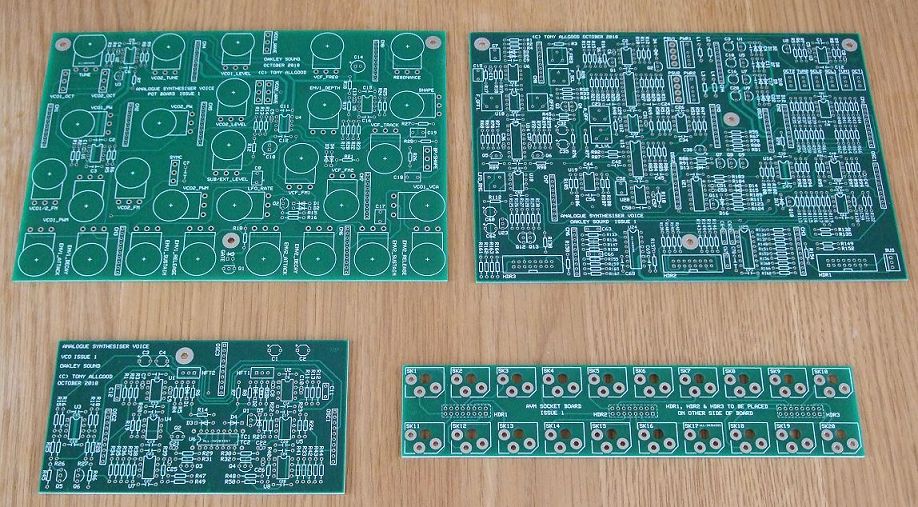
The original issue 1 PCB set. Later issue
boards are similar.
Prices
Click
here for ordering details.
ASV Main Board issue 1.2 PCB
…………………………………. 30GBP
ASV Pot/switch board issue 1.3
PCB ………………………….. 20GBP
ASV Dual VCO Board
issue 1 PCB …………………………….. 15GBP
ASV Socket board issue
1.1 PCB ………………………………… 8GBP
1K +3300ppm/K temp co resistor (pack of three) …………….. 6GBP
All four PCBs are required to make one ASV
module.
MU Shim panel
……………………………………………………….. 10GBP*
* The shim panel is only needed if you are
using a thinner MU panel similar to that which was available from
Re:Synthesis.
All other parts can be purchased from your usual
electronic component supplier with the exception of the AS3310 which is
available from Electric Druid, Thonk and others.
All prices include VAT at UK rates. Shipping
is additional to these prices. See also the
FAQ page.
Downloads
Before building any Oakley project please
ensure you have the most up to date documentation.
Construction
Guide Our handy guide to building
Oakley DIY projects
Parts
Guide Our handy guide to buying
parts for Oakley DIY projects.
Schematics are available to
purchasers of the PCBs and will only be sent via e-mail when the
board(s) are shipped.
Front Panel Database
You can edit these to suit
your own panel design or print it out to use as a drilling
template.
ASV.fpd Frontplatten Designer file for 5U wide MOTM format
module.
To read these files you will need
a copy of ‘Frontplatten designer’ from Schaeffer. The program also features on-line ordering. The
company are based in Berlin in Germany and will send out panels
to anywhere in the world. Delivery to the UK normally takes
around ten days. For North American users you can also order your
Schaeffer panels from Front
Panel Express.
For technical support on all Oakley
projects please refer to the knowledgeable and helpful Oakley Sound Forum
which is hosted at ModWiggler.com. Tony
Allgood does not provide official building support for Oakley
projects, but he and many others are usually available for help
via the forum.
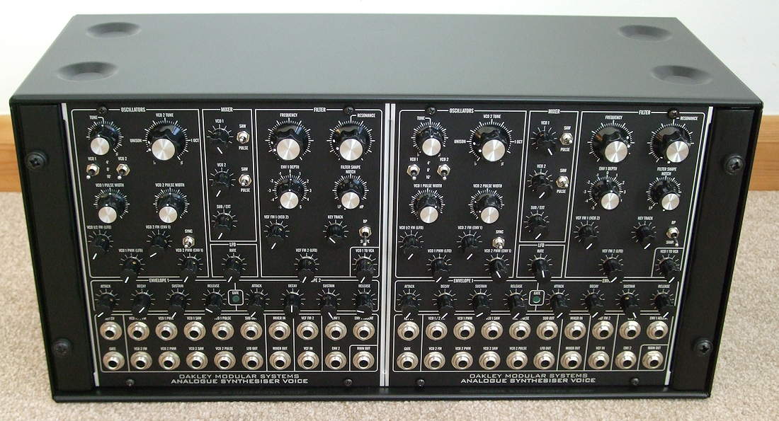
Two MU format ASVs fitted into a 5U high 19″
rack case from ‘All Metal Parts’ with Synthesizers.com’s 19″
rack rails to hold the modules in place. This particular case is
200mm deep. The smaller control knobs are Davies 1900H clones.
The power supply is built onto a 5U blank panel fitted to the
rear of the case.
Back Home: Oakley Sound