
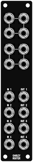
The
Oakley Router is a simple but useful module. The top section is
two passive multiples. A multiple, or ‘mult’, is a number of
sockets, in this case four, that are connected together in
parallel. It can be used to send one output to up to three other
destinations, splitting the input signal into three. This is
useful for sending, for example, the gate output of a midi-CV
convertor, to three envelope generators so that all three
envelopes trigger together. Or a single sawtooth output from one
VCO to two filters for parallel processing.
The
lower section contains four identical inverting amplifier
circuits. The amplification can be set when building the unit but
the suggested gains are either -1, -0.33, or -0.1*. Each output
is balanced and uses a 1/4 TRS (tip ring sleeve) socket
which can be connected directly, using a balanced cable, to a
balanced input of an audio interface or mixing desk without
introducing ground loops. The outputs can, however, also be used
with unbalanced inputs, and the outputs will not be damaged if
you use standard mono unbalanced (TS) cables.
Each
of the output amplifiers are inverting, that is a positive going
signal is turned into a negative going signal. This has no
audible effect on the audio signal but will change the polarity
of any control voltages passed through it. The module could thus
be used as an effective quad inverter if required.
*
Some audio interfaces and most guitar effects pedals distort with
the high signal levels coming from a modular synthesiser so
reducing the signal level can aid interfacing troubles. For audio
interfaces that have such problems I recommend the gain be set to
-10dB which is a voltage gain of 0.33. For guitar pedals it is
best to reduce it to a tenth of the original signal which is
voltage gain of 0.1. Each of the four output stages can have a
different gain if required.
The
module is built from two printed circuit boards (PCBs), the
larger socket board and the smaller four layer main board. Both
boards are required to build the project and are sold as a set.
The
module accommodates either our standard Oakley/MOTM power header
or a Synthesizers.com power header. Current consumption is +/-16mA
at +/-15V.
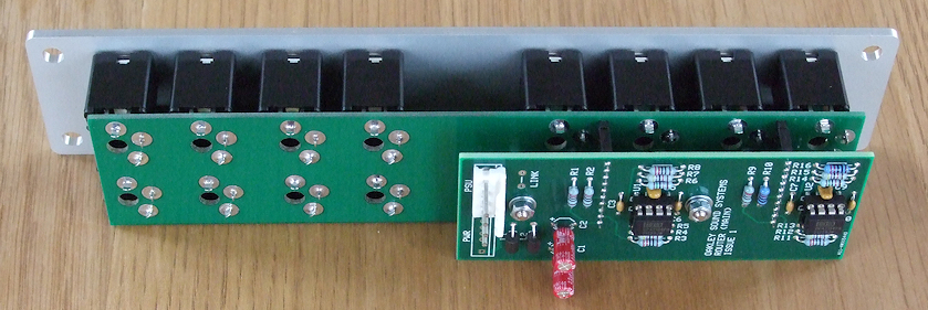
This
shows the module built behind a 1U wide natural finish Schaeffer
panel. The two boards are connected together via two 10-way SIL
headers and sockets.
Project Downloads
Construction
Guide Our handy guide to building
Oakley DIY projects
Parts
Guide Our handy guide to buying
parts for Oakley DIY projects.
Schematics are available to
purchasers of the PCBs and will only be sent via e-mail when the
board(s) are shipped.
Front Panel database
A Schaeffer front panel can be made for
this module. The databases can be found by downloading the
following links:
5U format 1U wide
Router module in traditional black
5U format 1U wide
Router module in natural (silver) finish
To read these files you will need
a copy of ‘Frontplatten designer’ from Schaeffer. The company are based in Berlin in Germany and
will send out panels to anywhere in the world. Delivery to the UK
normally takes around ten working days. For North American users
you can also order your Schaeffer panels from Front
Panel Express.
Back home