
Discontinuity – Waveshaper, Wavefolder,
Clipper, Ring Modulator & Wavesplicer
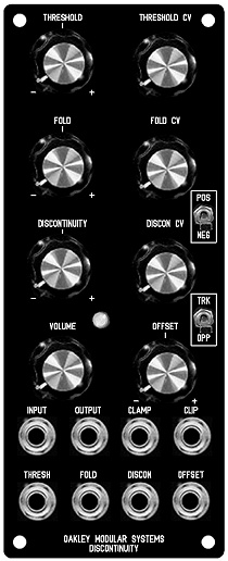
The Discontinuity is the updated version of
an older Oakley module called the Wavefolder. It is a voltage
controlled waveshaper module designed primarily for use in
modular analogue music synthesisers. The module comes in the
standard 5U high 2U wide format which is directly compatible with
MOTM series but can be built as a double width MU module too.
The Discontinuity module, although using the same core technology
as the old Oakley Wavefolder, is different enough in circuitry,
usage and front panel design to be worthy of a new name. And it
is these additional discontinuity and offset controls and CV
inputs that make this module very unique.
Waveshaper modules work very differently to, and perhaps less
intuitively than, other sound shaping modules such as filters,
ring modulators and amplifiers. As such the Discontinuity will
take some time to get used to. However, when used to process
simple VCO waveforms it is capable of creating some very
beautiful tones, all of which can be varied dynamically in
musically interesting ways. Input waveform type, whether triangle,
sawtooth or sine, can have profound tonal differences in the
Discontinuity’s output. And varying the input level can also have
some amazing affects.
Internally the module is arranged as five sections connected in
series.
1. The Soft Clipper. This
circuit gently restricts all input signals to around +/- 5.5
volts peak. Its essentially mimics an overdriven valve or tube
amplifier. The output of this circuit passes directly to the next
stage which is…
2. The Clamper. This prevents the output from
going above or below a preset limit. Unlike the soft clipper
circuit the clamping is hard and abrupt. And unlike the soft
clipper the limit is completely voltage controllable. We call it
the Threshold and it can be controlled with a front panel pot or
input CV. Any input can be altered dramatically with this
function. As well as being passed on to the next stage of the
module, the output of clamper is available at its own output.
A three way toggle switch, called ‘polarity’ although not marked
as such on the front panel, offers three modes of clamping:
a) POS the input
signal is clamped when it exceeds the threshold voltage. ie. if
the threshold voltage is 2V, then all parts of the input signal
that go above 2V will be clamped.
b) NEG the input signal is clipped when
it falls below the inverse of the threshold voltage. ie. if the
threshold voltage is 2V, then all parts of the input signal below
-2V will be clamped.
c) BOTH the switch is in its middle
position. Both negative and positive clipping takes place. ie. if
the threshold voltage is 2V, then all parts of the input signal
above 2V are clamped, and all parts of the input signal below -2V
are clamped.
The three polarity modes, positive,
negative and both.
In the old Wavefolder when the signal was
clamped the output signal was simply held at the threshold
voltage. In the Oakley Discontinuity the output level during
clamping can now be varied dynamically. This can be done either
as a function of the threshold voltage, via the module’s
Discontinuity control and its CV input, or as a fixed offset with
the Offset control and its CV input. Furthermore, the offset can
either be applied symmetrically or asymmetrically depending on
the Track/Oppose switch. What this means is that we can actually
remove any proportion of the original signal at that point where
it exceeds the threshold voltages and replace it with another
input. In other words we can splice one waveform in place of
another. This has the potential to make some very new and
wonderful timbres.
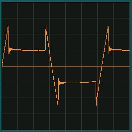
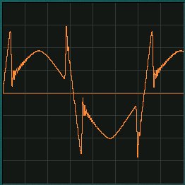
Discontinuities being introduced by a) the
Discontinuity pot b) the offset control in Oppose mode.
3. The Clipper. What the
Clamper bites off, the clipper returns. The Clip output is the
part of the original input signal that gets chopped off by the
clamper circuit. So if you put a 5V peak triangle waveform into
the Clamper, set the threshold to be 2.5V and set the mode switch
to BOTH, the Clamp output will give you the neatly clipped almost
square wave output, while the clipper will give you the tips of
the pointed bits of the original triangle waveform.
4. The Folder. The Discontinuity’s fourth
section is based around a four quadrant multiplier or ring
modulator. Here the Clip out and Clamp out are mixed together.
However, the clip output may be added or subtracted from the
clamped signal. A pot and an external CV sets the mix ratio and
polarity. Again, consider the 5V triangle waveform with the
polarity switch set to either POS or NEG. With the Fold pot set
to 0, you get the plain Clamped signal at the main output. Turn
the Fold pot clockwise and the clipped signal will return to
create the original signal once more. But keep turning it, and
the clipped signal is now bigger then the original. Now turn the
pot the other way. The clipped signal gets subtracted from the
clamped signal. You can get full wave rectification, thus your
triangle becomes another triangle at twice the frequency.
Multiplication. Turn it up further and more harmonics come in.
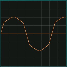
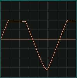
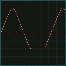
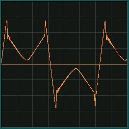
The fold parameter controls the gain of
waveform that exceeds the threshold voltage. In the left picture
we see the gain set to slightly less than one. In the right
picture the gain is now negative resulting in the waveform being
folded back on itself.
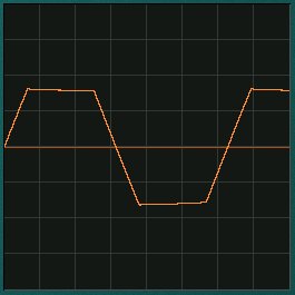
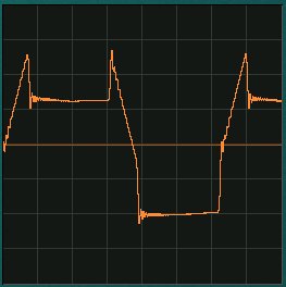
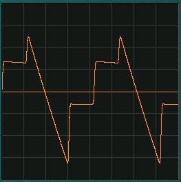
These two pictures show the output with
both folding and a discontinuity applied. The left shot shows the
fold gain at around 50%, while the right hand shot shows a gain
of around -50% and thus folding back on itself.
5. The Amp. The last stage
is a simple x10 amplifier. The Discontinuity can clip accurately
down to small levels if you want, so you need a good amplifier to
bring it up to a decent level again.
And don’t forget the Discontinuity will
work with any signal, audio and CV. You can mangle EG outputs,
LFOs and, of course, your VCO. Different waveforms will be
treated in very different ways.
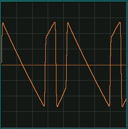
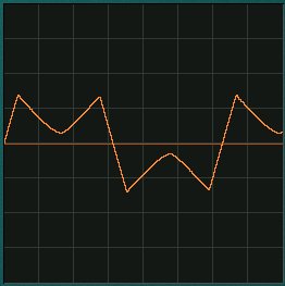
These two shots show sawtooth waveforms
being clipped, discontinuitied and folded. A great many new and
interesing timbres and modulations can be created.
The module accommodates either our standard
Oakley/MOTM power header or a Synthesizers.com power header. The
unit requires +/-15V and takes a maximum of 60mA from the
positive rail and slightly less from the negative rail.
Sound Sample Downloads
All samples used a minimum of
one Oakley VCO, one Oakley VC-LFO for modulation and a midiDAC
for control. Recordings were done dry except where stated.
Triangle wave input. Negative
and positive clipping, ie. no folding or discontinuity. Manual
and then VC-LFO modulation of threshold voltage.
Triangle wave input. Negative
and positive clipping with threshold kept static. Manual movement
of Fold pot and then VC-LFO modulation of fold parameter
Sawtooth wave input. A
combination of folding and clipping to alter a sawtooth to a ramp
waveform via various discontinuous waveforms.
Triangle wave from VCO1 to
main input, Sinewave one octave down from VCO2 to Offset input.
Manual control of threshold to move from one VCO to the other.
Some additional filtering from a COTA module and shaped with an
ADSR. Stereo echo effect added to provide ambience.
Sine wave inputs from two VCOs
to create a ring modulation effect. The modulation VCO is
connected to the Fold CV input and its frequency is manually
tweaked as the clip progresses. The Fold pot is centralised,
except towards the end of the clip, and the Threshold and
Discontinuity pots are set fully anti-clockwise.
Triangle wave input. Repeating
sequence using an ADSR into the Fold CV input while manually
tweaking parameters. A little echo FX is provided for ambience.
Sawtooth wave input. An ADSR
is used to modulate the fold parameter and shapes the output from
sawtooth to a triangle wave to create filter sweep type effects.
Project Downloads
Discontinuity
issue 3 Builder’s Guide
Construction
Guide Our handy guide to building
Oakley DIY projects
Parts
Guide Our handy guide to buying
parts for Oakley DIY projects
Schematics are only available
to purchasers of the PCB and will be sent via e-mail when the
board(s) are shipped.
Front Panel database
A Schaeffer front panel can be made for
this module. The databases can be found by downloading the
following links:
5U format in
traditional black
To read these files you will need
a copy of ‘Frontplatten designer’ from Schaeffer. The program also features on-line ordering, so it’s
easy to buy your panels from Scheaffer.
The company are based in Berlin in Germany
and will send out panels to anywhere in the world. Delivery to
the UK normally takes around ten days. For North American users
you can also order your Schaeffer panels from Front
Panel Express.
Back home