
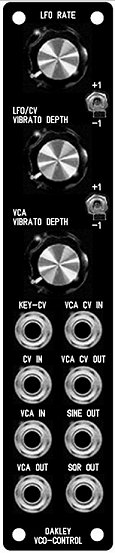
1U wide suggested panel layout for those
with Oakley CV/gate Bus fitted. Those without CV/gate bussing can
simply use a different socket choice – perhaps foregoing the VCA
CV OUT and SQR OUT for KeyCV-A and KeyCV-B;
The Oakley VCO Controller is a
1U wide module designed to function as a master controller for
two or more VCOs.
The basic premise of this
module is to make it easy to control multiple oscillators. Quite
often you will require simple vibrato of two or more VCOs.
Normally this is done by patching one LFO (low frequency
oscillator) to your VCOs via a multiple. This uses up a minimum
of three patch leads for two VCOs and the vibrato depth needs to
be set individually on each VCO. With this module the internal
sine wave LFO is piped directly to the VCO’s control bus, or
optional output sockets. One pot controls the depth of the LFO
for both or more VCOs. The LFO may be overridden by inserting a
jack into the CV IN socket on the module thus allowing other CVs
to control multiple VCOs simply.
The VCO Controller also
features an inbuilt VCA (voltage controlled amplifier) module.
This allows the internal LFO, or any external CV, to be
controlled by another CV. This CV may be aftertouch or modulation
wheel outputs from your midi-CV interface. Thus, vibrato depth
can be controlled with your keyboard or keyboard’s wheel or lever.
Only one patch lead is required to add touch sensitive or wheel
controlled vibrato to your patches normally this would
require a minimum of 2U of rack space, a multiple, and a whole
bunch of patch leads.
The VCA within this module can
also be used separately as a ordinary VCA should you not wish to
use the other features in the module at any time.
Also available are two octave
switches. These affect the two KeyCV outputs of the module
individually. This each VCO, or VCO bank, can be raised or
lowered by one octave at a flick of a switch. Each KeyCV output
uses a low impedance cable driver to ensure no droops with long
signal runs and multiple loading.
Although this module was
designed to work with the Oakley bus*, which pipes around KeyCV
and gate signals around your modular, the input and output
sockets on this module can be assigned different purposes so as
to suit individual requirements.
VCA control input is
optionally low pass filtered so as to reduce stepping artefacts
from midi generated CVs. This low pass filtered output is
available via the VCA CV OUT socket so you can use it to control
other modules.
The internal LFO outputs are
available individually from the front panel as both sine wave
(+/-5V) and square wave (+5V, 0V).
* The Oakley bus is a three
way connector found on various modules. Pin 1 carries the
keyboard CV (note control) and pin 3 carries gate (note on or off).
The VCO Controller module taps into the Oakley bus and creates
two new busses for each VCO bank. It also has a bus through
feature for easy wiring. Please see the Dizzy User Guide for more
information about the Oakley Bus.
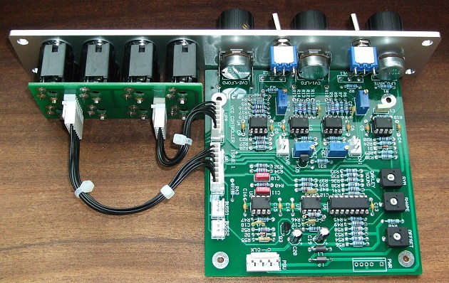
The original issue 1 VCO Controller board
with optional Sock8 board.
Issue 2 boards are similar. The Sock8 makes wiring the sockets
very easy. The optional Bus1 and Bus2 headers connect to the
midiDAC’s buss output or to the system Dizzy board. The CV1 and
CV2 three way headers in the middle of the board go to the VCO
bus inputs.
For DIY builders of this
module it is possible to purchase the Sock8 circuit board which
is available separately. This little board speeds up the wiring
of the eight 1/4″ sockets and reduces the chances of any
wiring errors.
Power (+/-15V) is provided to
the board either by our standard Oakley 4-way header or
Synthesizers.com header. Current consumption is approximately 20mA
per rail.
The board size is 107mm (high)
x 110mm (deep).
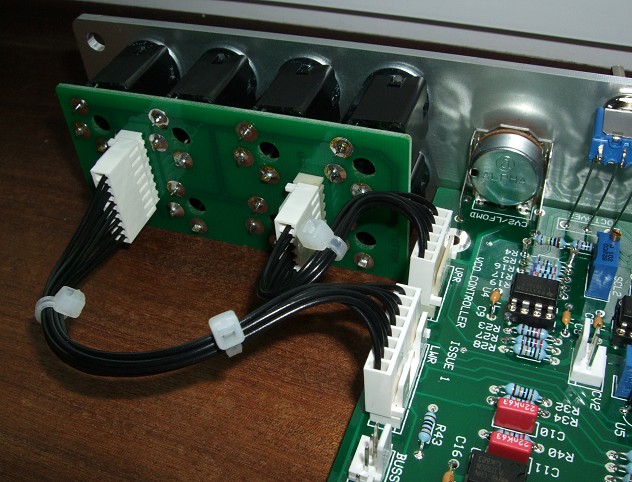
A close up of the interconnections between
the module board and the optional Sock8 board.
Project Downloads
VCO
Controller Builder’s Guide
Construction
Guide Our handy guide to building
Oakley DIY projects
Parts
Guide Our handy guide to buying
parts for Oakley DIY projects
Schematics are only available
to purchasers of the PCB and will be sent via e-mail when the
board(s) are shipped.
Front Panel database
A Schaeffer front panel can be made for
this module. The databases can be found by downloading the
following links: