
Constructional Difficulty: Moderately Easy
This is an effective CV and audio processor that features two comparators and a gate delay circuit in a compact 1U panel design.
Dual Comparator
A comparator is a functional circuit block that allows two signals to be compared with one another. The output of the comparator is either high (+5V) or low (-5V) depending on which signal is more positive than the other.
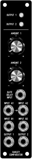
Each comparator has two inputs, input A and input B. Input B is directly controlled by a reversible attenuator that affects the level of the signal fed to the comparator circuit block. A reversible attenuator can not only alter the level but also the polarity of the signal too. With the pot in the positive direction, the output of the comparator will be +5V if the input A is more positive than the attenuated input B. If input B is more positive than input A, then the output is -5V. A LED will light when the output is in the high state.
If no jack is inserted into the input B, then input A will be compared to a fixed voltage. This fixed voltage is controlled by the pot, and can be set to anything between -7V and +7V.
The output of the comparator can be treated as either an audio signal or as gate signal to control envelope generators and sync LFOs.
Dual Gate Delay
If no jack is inserted into one of the input A sockets, then you can use that channel as a gate delay circuit. Inputting a standard gate signal into the ‘gate delay input’ will cause the output of the comparator to go high after a certain length of time. That length of time is controlled either by the appropriate ‘amount’ pot directly, or by a voltage present at input B which can then be controlled by the ‘amount’ pot. The gate may be delayed by around 5mS to around 5 seconds.
Both comparator channels are fed from the same gate delay circuit, so you can simply set up two different delays from one gate. This can be used to create multiple triggers from a single ‘note on’ event.
Please note: in common with most gate delay circuits the delayed output will immediately drop low when the gate goes low. Thus the gate delay process affects only the start of the note, not the end.
Uses
This compact and versatile module can be used for a variety of purposes. These are some examples of its use in a small to medium size modular:
- To create delayed gate signals for pseudo echo effects.
- To create powerful multiple phase pulse width modulation from triangle or sawtooth VCO/LFO outputs.
- To create a voltage controlled switch in conjunction with a VCA.
- Creating hard distortion effects from an audio signal.
- Creating random gate events in conjunction with the Oakley Noise/Filter module.
The main PCB is 104mm high x 104mm deep. Power (+/-15V) is provided to the board either by our standard Oakley 4-way header or Synthesizers.com header. Current consumption is approximately 35mA per rail.
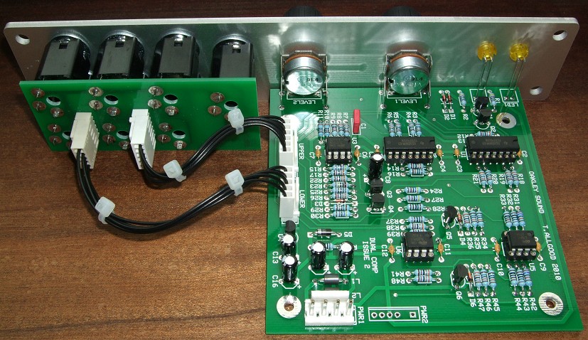
The view behind the panel.
Sound Sample Downloads
Two examples of multiphase pulse width modulation. These two samples use one VCO being fed into the dual comparator module. Each comparator section is being fed by a separate triangle wave LFO. The first sound you hear is the PWM output of the VCO, itself driven by its own LFO. Then the first comparator output is added and then finally the second. You can hear a very rich sound coming from just one VCO.
Single note drone
Simple sequence
Two examples of the dual gate delay firing two additional EGs. In each sample you will hear just four key presses. There are three simple attack-decay EG sweeps of the filter. The gate pulse triggers one EG, shortly followed by the first delayed gate triggering the second EG, then the final sweep is heard as the third EG is triggered. Both samples were recorded using two sawtooth VCOs fed into a Superladder filter.
Prices
This board has been discontinued.
Click here for ordering details.
Comparator main PCB issue 2 …………………………. 16GBP Sold out
Comparator socket board issue 2 ………………………. 5GBP
Comparator pot bracket kit ………………………………… 0.50GBP
Theoptional Pot Bracket Kit contains the two 16mm Alpha pot brackets required to complete one module.
All other parts can be purchased from your usual electronic component supplier.
Project Downloads
Construction Guide Our handy guide to building Oakley DIY projects
Parts Guide Our handy guide to buying parts for Oakley DIY projects
Schematics are only available to purchasers of the PCB and will be sent via e-mail when the board(s) are shipped.
Front Panel database
A Schaeffer front panel can be made for this module. The databases can be found by downloading the following links:
5U format in traditional black
To read these files you will need a copy of ‘Frontplatten designer’ from Schaeffer. The program also features on-line ordering, so its now even easier to buy your panels from Scheaffer.
The company are based in Berlin in Germany and will send out panels to anywhere in the world. Delivery to the UK normally takes around ten days. For North American users you can also order your Schaeffer panels from Front Panel Express.