
The Oakley Discrete Ladder Filter (DLF) is
my reworking of the classic 1960’s low pass filter module.
Inspired by the circuits of the 904A filter and CP3 mixer, the
DLF combines them into one excellent sounding 6HP wide module.
The audio signal pathway is almost all
discrete components with a dual IC op-amp only providing the
input and output signal processing for the drive control.
Before entering the 904A style filter core,
the audio signal passes through a clone of the CP3 mixer. The
original CP3 module had two outputs, an inverted output and a non
inverted output. Apart from the change in phase, the two outputs
sounded different to one another when the input signal was
particularly loud and the output of the CP3 started to clip. The
distortion heard when clipping takes place is both unique and
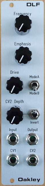
musically interesting. The Oakley DLF has a front panel switch to
select which of the input stage’s two outputs go on to the filter
circuit, Mode A or Mode B. The DLF’s input stage has been
designed to start to clip when the input signal is around +/-4V,
but keeping the signal below this will ensure a clean signal.
Turning up the DLF’s Drive control allows
the filter core to be overdriven, without changing the output
volume, and dramatically changes the sound at higher resonance
settings. The Drive control only affects the filter core and has
no affect on the input stage. So with variations in input level
and drive level it is possible to utilise the overdrive
characteristics of only the input stage, only the filter, or both
for a really heavy sound.
The filter will self oscillate at high
resonance. However, like the original module, the filter won’t
self oscillate much below 75Hz. When sweeping the filter’s cut-off
frequency at high resonance, this limited resonance at low
frequencies gives the filter a powerful bass sound.
Although
the module can be used as a filter module on its own, it is
expected that you use an external mixer, such as the Oakley Multimix, to combine and control the audio levels
going into the module.
Two control voltage (CV) inputs are
available on the front panel. CV1 offers the standard 1V/octave
control over the cut-off frequency. While CV2 has a depth control
which can be varied from off to up to 0.5V/octave, and has
additional switch that can invert CV2 if negatively going sweeps
are desired.
The module requires +/-12V and has a
current consumption of +60mA and -50mA.
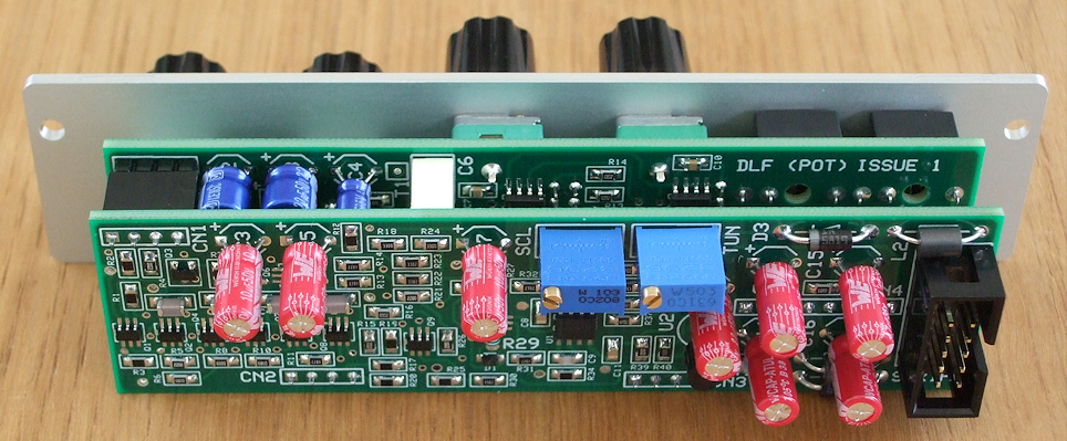
The PCB Set
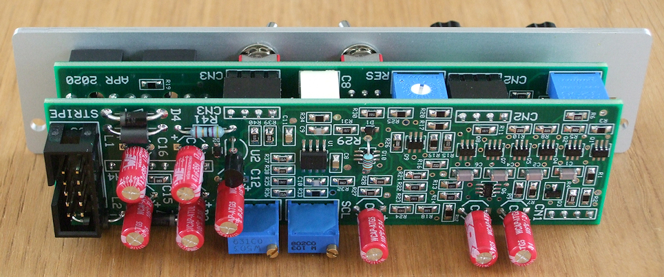
The DLF module comprises of
two printed circuit boards (PCBs) connected together with four 0.1
(2.54mm) single in line (SIL) headers and sockets. The main board
on the rear of the module houses the power input and conditioning,
the filter core, and CV processing circuitry. The pot board has
the pots, switches, and sockets that are attached to the front
panel, as well as the discrete input stage, overdrive circuitry
and CV2 processing circuit. To achieve good circuit performance
in a small space both boards are four layer designs. Each board
is the same size; 29 mm x 107 mm.
The
majority of the components are surface mount parts. The dual op-amps
are SOIC, while the resistors and surface mount capacitors are
0805. The dual matched transistors are in small SOT457 packages.
There is no requirement to hand match transistors. All components
are standard parts.
Sound Samples
All the following samples use an Oakley D-VCO
which connects to an Oakley Multimix and then to the DLF. The
output of the DLF is fed into an Oakley Classic VCA and both the
DLF and VCA are each controlled by an Oakley Envelope.
Here are three bass notes using the DLF at
high resonance. The drive is at minimum for the first note, half
way around for the second note, and on full for the second note.
This one plays back a simple sequence while
the controls of the DLF are manually tweaked.
A single note drone with the DLF almost in
self oscillation. The frequency and drive controls are manually
swept. Notice how driving the filter core harder in the second
half reduces the self-oscillation. Some reverb has been added for
ambience.
A dry sample of a simple sequence being
played while the emphasis control is changed.
Another sample of a simple two note octave
sequence being played while the emphasis control is increased and
decreased.
A more complex sequence with the frequency
and envelope depth controls being manually tweaked. A little
delay has been added for a bouncy effect.
Here we hear a single triangle wave with
the filter’s frequency control turned up full and the emphasis
control at its minimum. We are therefore listening to the effects
of the input stage in Mode B as we firstly increase the signal
level so the input stage starts to clip, and then, using the
Multimix’s ability to add an offset voltage, how that clipping
can be turned on harder to change the sound even more.
Project Downloads
Builder’s Guide Parts
Lists, calibration and building information
Construction
Guide My handy guide to building
Oakley DIY projects
Parts
Guide My handy guide to buying
parts for Oakley DIY projects
Schematics are only available
to purchasers of the PCBs and will only be sent via e-mail when
the boards are shipped.
Front Panel database
A Schaeffer front panel can be made for
this module. The database can be found by downloading the
following link:
6HP Eurorack format
in natural silver
To read, edit and print these
files you will need a copy of ‘Frontplatten Designer’ from Schaeffer. Panels can be ordered via the program using its
web based ordering system.
Schaeffer are based in Berlin, Germany and
can send panels to anywhere in the world. Delivery to the UK
normally takes around ten days. For North American users you can
also order your Schaeffer panels from Front
Panel Express.
Back to projects page: Projects
Back home