
Oakley ADR30 – Analogue Delay Line and Chorus Module
Construction difficulty: This is a
moderately large project on a four layer circuit board. An
oscilloscope is recommended for calibration.
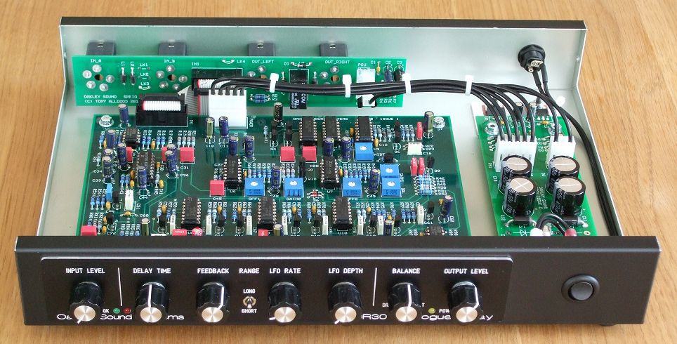
This build uses a Takachi YM-300 case with
an engraved metal overlay for the front panel legending from
Scheaffer. Both the SREIO socket board and RPSU power supply
module have been fitted.
The Oakley Sound Systems ADR30 is an
analogue delay module that processes audio signals to create echo
and chorus effects. It uses two Xvive MN3005 bucket brigade delay
(BBD) integrated circuits to produce a very distinct ‘vintage’
sound. Classic companding noise reduction circuitry further adds
to the sonic characteristics.
Delay time is controlled by a single
control on the front panel as well as a built in low frequency
modulation oscillator and/or an external control voltage. With
short delay times using the modulation oscillator can create both
subtle and deep chorus effects. A front panel switch controls
whether the signal runs through one or both MN3005 devices. Anti-aliasing
filtering is achieved by two 6-pole discrete switched capacitor
low pass filters that track the delay time, giving the maximum
audio bandwidth for the specific delay time. Thus short delays
remain reasonably bright sounding while longer delays become
increasingly dark. Delay time can be varied continuously from 15ms
to 300ms in short mode, and 30ms to 600ms in long mode.
The board is sized so that two can be
fitted next to each other in one 1U high 19″ rack case.
The unit is mono but features separate
outputs for the wet/dry signal and the delayed signal. The audio
input and outputs are balanced but are compatible with non
balanced connections. A two LED level meter helps you keep signal
levels at optimum ensuring a respectable signal to noise ratio
without clipping. The unit will not be damaged by driving the
unit into overdrive and interesting sounds can be obtained by
deliberately doing so, either by turning up the input level or by
allowing the feedback to build up to self oscillation. Although
the unit does feature noise reduction circuitry the delay line
devices are inherently noisy and have a very restricted bandwidth.
The signal will deteriorate in an interesting manner as the delay
time is increased and/or feedback is heavily applied.
Two MN3005 re-issue BBDs provide the
analogue delay pathway. A swtch on the front panel determines
whether the signal runs through one or both BBD chips.
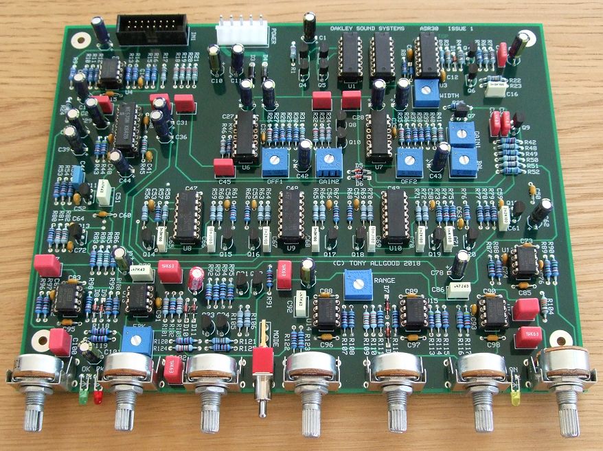
The ADR30 PCB is 198mm wide and 153mm deep
and is a four layer design using only through hole components and
no difficult to get parts. The unit could be built into a 1U high 19
rack enclosure – although the PCB only takes up half that width.
Two units could be fitted side by side in a 1U 19″ rack
although the case must be deep enough to accomodate the power
supply and the I/O sockets. Alternatively, the project could be
housed in one of the many standalone enclosures available such as
the low cost Takachi YM-300.
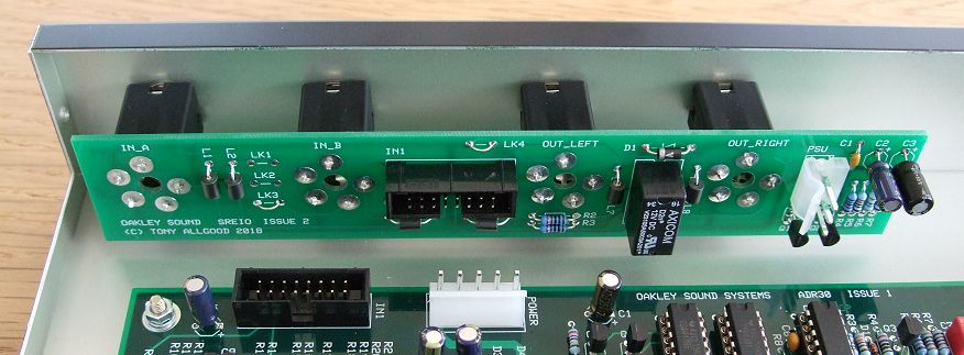
The ADR30 main board can be wired to its sockets
directly if desired but an optional I/O board, called the SREIO,
is available which makes wiring easier and also has a relay based
anti thump circuit.
An optional input/output board, the SREIO,
is available to go with the ADR30 main board. This features space
for three Switchcraft 114BPCX and one 112APCX socket and has a
relay controlled muting circuit to reduce thumps on the audio
outputs when the power supply is switched on and off. The power
to the unit should be a regulated split supply of +/-15V. Power
is admitted onto the main circuit board via a five way 0.156
(2.96mm) header of MTA or KK type. Power consumption is +80mA and
-50mA at +/-15V. Although you can use any quality +/-15V power
supply an optional power supply module has been created for the
ADR30 called the RPSU. This is can be powered from an external
500mA 15V AC output mains adapter. Alternatively, an internal
mains transformer can be used with the RPSU if you have
sufficient knowledge on how to install one safely. The RPSU PCB
is 150mm x 51mm.
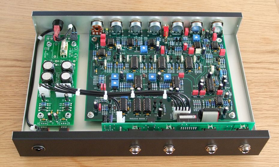
The
prototype ADR30 built into a Takachi YM-300 case with an Oakley
RPSU module providing power.
Sound Samples
Single bass note processed
with the ADR-30. The internal LFO is modulating delay time while
the feedback control is manually altered.
Single hits (basic VCO/VCF/VCA
combo) with delay time being manually controlled to produce pitch
shifted echoes.
Single random note hits with
delay time modulated by the internal LFO while altering the
amount of feedback.
Low frequency drone manually
gated by the input level control and then left to recycle with
the feedback set to self-oscillate.
Another drone, this time
altering the cut-off frequency of the filter and then on the ADR30
manually introducing LFO modulation and adding feedback.
Some plucky notes manually
played and processed through the delay line while altering the
delay time.
White noise filtered with a
low pass filter controlled by a fast decaying envelope triggered
by hand. The delay time and feedback controls on the ADR30 are
manually altered
Prices
ADR30 issue 1 PCB
………………………………………………. 35GBP
SREIO issue 2 PCB
…………………………………………………. 8GBP
RPSU issue 2.1 PCB
……………………………………………… 12GBP
ADR30 Pot Bracket Kit
…………………………………………….. 1.75GBP
1K +3300ppm/K temp co resistor
…………………………….. 2GBP
The ADR30 pot bracket kit
contains seven special pot brackets. The brackets are used to
hold the PCB mounted Alpha and ALPS pots safely to the PCBs. They
are not required if you are using different types of pots or hand
wiring any pots to the board.
Most of the other parts should be able to
be purchased from you usual electronic component supplier. Please
see the Builder’s Guides for more details.
See the Oakley Sound ordering
page for ordering information, shipping charges and payment
methods.
All prices include VAT at UK rates.
Shipping/postage is additional to these prices. See also the FAQ page.
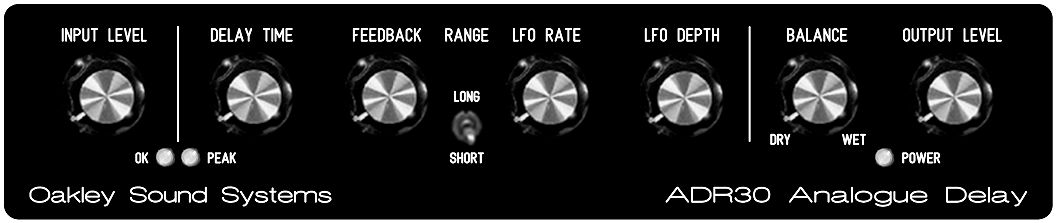
A simple render of the suggested panel
layout.
Downloads
Before building any Oakley project please
ensure you have the most up to date documentation.
Construction
Guide Our handy guide to building
Oakley DIY projects
Parts
Guide Our handy guide to buying
parts for Oakley DIY projects.
Use ‘save as…’ button to
download and view the files.
The schematic is provided only
to purchasers of the printed circuit board. This will be sent to
you as a PDF file with your shipping confirmation e-mail.
Front Panel databases
You can edit these to suit
your own panel design or print it out to use as a drilling
template.
ADR30.fpd Frontplatten Designer file for the suggested panel
overlay suitable for a 1U rack case.
ADR30_YM300.fpd Frontplatten Designer file for the suggested panel
overlay suitable for the YM300 case.
RPSU_shim.fpd Frontplatten Designer file for the suggested
heatsink shim plate.
To read these files you will need
a copy of ‘Frontplatten designer’ from Schaeffer. The program also features on-line ordering. The
company are based in Berlin in Germany and will send out panels
to anywhere in the world. Delivery to the UK normally takes
around ten days. For North American users you can also order your
Schaeffer panels from Front
Panel Express.
For technical support on all Oakley
projects please refer to the knowledgeable and helpful Oakley Sound Forum
which is hosted at ModWiggler.com. Tony
Allgood does not provide official building support for Oakley
projects, but he and many others are usually available for help
via the forum.
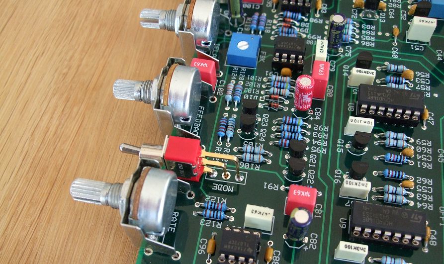
All
front panel components are soldered directly onto the board which
makes building straightforward.
Back to the start page